Seeing that last month was a particular happy and also a very dark period for the project, at least things are looking better as I type this.
Here is my list of issues/improvements to fix or at least diagnose and understand it better. In the next few updates, I will work thru the list:
- Motor: fix combustion chambers, reassemble
- Fuel Lines: new 10mm OD x 8.5mm ID steel lines into -6 flex line thru -6 bulkheads, a much bigger and better setup.
- Oil Cooler: relocated to the front of the radiator, add an hot air separator between it and the air filter, -8 lines swopped for -10 flex lines.
- Induction upgrades: Stock SR20VE Throttle to small, will install BMW E46 M3 throttles with new velocity stacks and plenum
- TPS: starting to show signs of aging, will be replaced with new E46 unit as they actually have a O-ring to keep the insides water tight, good idea on a rally car.
- MAP Sensor: will be moved to the engine bay closer to the ITB’s
- New Suspension: all depends on time, but the front S13 parts will be swopped for MKII Escort Bilstein type Monotube setup, rear shocks will also be swapped for MKII rally units
- Wheel Speed Sensors: will be in place on the new front suspension
- Look at Digi Dash Config: will ask for some advice around the setup to get the unit to read from 0 km/h.
- Switches for Motorsport functions:
- Launch Control on D1-6
- Flat Foot Shifting needs lock out switch, basically ON/OFF for the limit switch
Seeing that I had some damage to the combustion chambers in the head from the screw’s Friday Party, I took the head to a company called HeadZone for cleaning, blending and finally a resurface of the head. Seeing that the company does not do their own porting, polishing and blending, this was done by one of their employees, thus it took way longer than I expected. But at the end of the day I’m quite happy about the work that was done. While all this waiting for the head was going on, I was busy with the following.


Fuel Lines
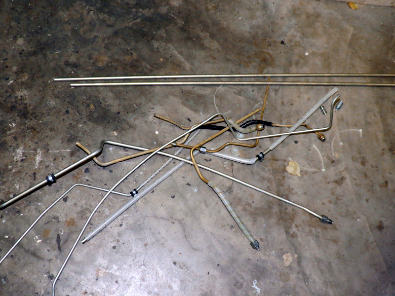
Work started with the fuel lines, the old ones was removed or I should rather say destroyed, all good and well for getting them out of the car, but once you sit with the new hard lines, pipe cutter and bender in hand, you quickly realise that it would have been much easier if you just kept the old ones in tact to use as samples. Well as you would have guessed, I sometimes get a little over eager to get some work done, this is exactly the situation I found myself. Seeing that I had nothing to work from, I actually got my chair and had a good long sit down next to the car to plan the new setup. Seeing that the old setup was quite difficult to get correct seeing that it run thru both the front and rear firewalls. This time around I decided to take the easy route, slightly more expensive and use bulk heads. The beauty about these is, you just drill the correct size hole, fit them thru the hole and fasten them, then you just fasten a flex line to them, as easy as that. I ordered some bulk heads and fittings for the oil cooler. Having made a decision to use bulk heads, I decided to use Parker brass push lock fittings and hose between the hard lines and bulk heads on the inside of the car, seeing that the hose is fire retardant, it will work 100%. Seeing that the old setup was way too small, 8mm OD feed and 6mm OD return, which yields an effective 6.2mm ID feed and 4.2mm ID return with the use of 0.9mm wall Zista tubing, this resulted in the regulator not being able to do its work effectively and quite considerable aeration in the lines. This time around I used 10mm OD Zizta tubing for the feed and return, which will not hinder the supply of fuel thru the flex lines of -6AN. Seeing that I had to start from scratch, I made a few changes in the route the lines follow to make it easier to fit and remove these. Two pairs of -6 Male plugs was drilled and silver soldered to the bend Zista tube and fastened to the vehicle. The only outstanding work to be done is the flex lines in the boot and in the engine bay, but I first have to finish the new induction before I’ll order the fittings.


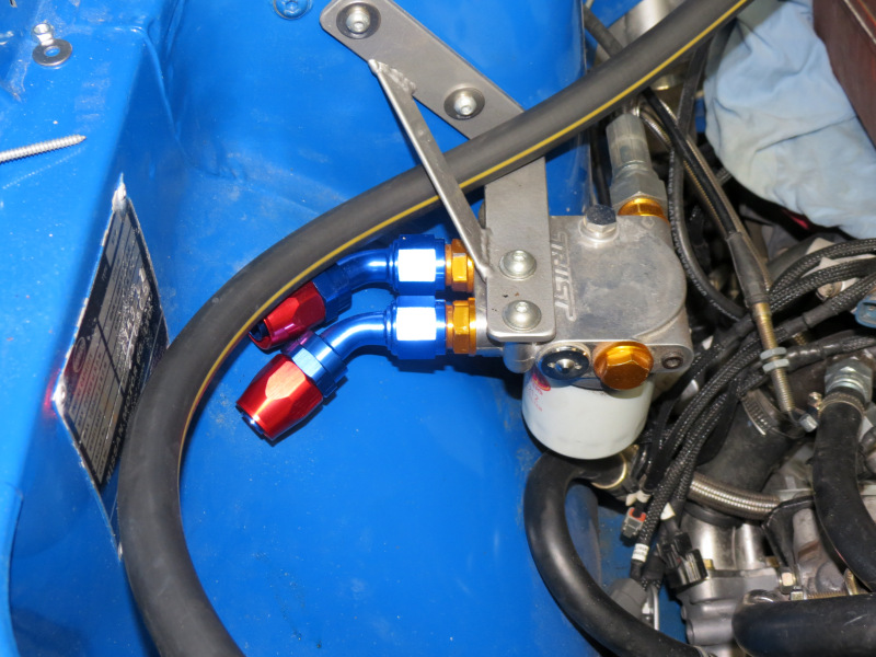
Oil Cooler
First order of business was to strip the front-end of the car to get easier access, especially since i was about to remount the oil cooler, a fixture that was mounted with the idea that it will never have to be removed. Once everything was stripped and cleaned, the only obvious place to remount the unit was next to the radiator fan, the only problem with that was the fittings that was then needed, seeing that the pipes had to turn between 150-180 degrees. I took my change and ordered some fittings for the oil cooler and thermostat housing, luckily at the end of the day the gamble paid off and it seems that everything will work out, just not 100% sure about the 45 degree fittings on the thermostat housing, as the space is limited. With the next order of fittings I’ll also order the black nylon braided hose to finish the relocation.

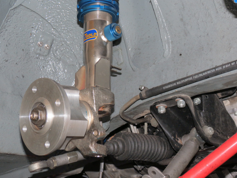
Front Suspension
While all the above was going on, I managed to strip the front right strut to start the measuring process for the new gravel rally struts. It was decided to convert the majority of the front suspension parts to legendary Ford Escort MKII units, this makes more sense than would have admitted a year ago, seeing that a friend is also building a MKII rally car, another a Escort Track car and my brother will use Escort parts on his new project, interchangeable parts could always become very important, especially on the rally cars. After numerous conversations we decided on the proven Bilstein Monotube setup, this replaced the original Escort strut with a new unit with a different strut tube to accommodate the Monotube inserts, which also provided the opportunity the strengthen the body to stub axle fixture. We got in contact with Gaz Shocks in the UK seeing that they do offer a package that is really exactly what we are after as their inserts are based on the Bilstein units but are available in an adjustable version also. I’ll also be replacing my rear shocks with a gravel rally version of the Escort Grp4 rear coil overs. After about 3 months of research we took the plunge and placed an order for 10 coil overs for 3 different vehicles. I’ve never seen such a vast amount of emails flying around to gather all the necessary detail. Hopefully these units will be in the country to the end of March.


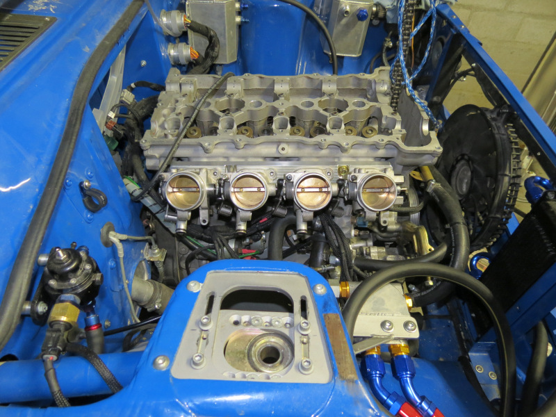


Independent Throttle Bodies
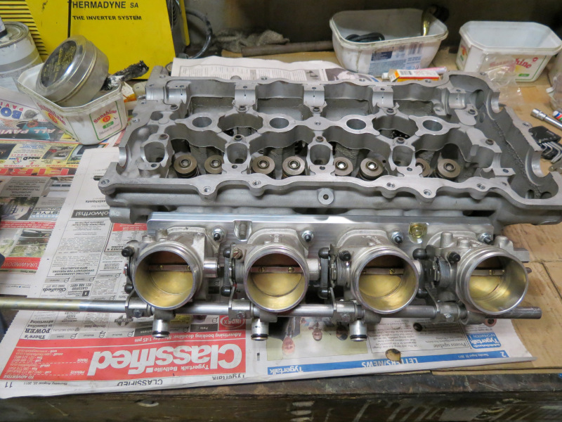
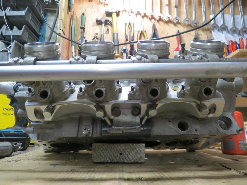
Seeing that Ian from RAW picked up that the intake manifold goes into vacuum on Wide Open Throttle in the higher rpm range, suggested that the standard throttle body is just not big enough to support the N1 cams, this on a motor that is otherwise stock on the intake side. Since I’m not a fan of my particular throttle since it developed a habit to cause me grieve, I decided to swop the entire intake for a new independent throttle setup, this time around I’ll use BMW E46 M3 throttle bodies linked to a sourced adapter plate designed for the SR20VE motor. I took the plunge and ordered the adapter plate and 4 throttle bodies, on arrival I opened the box to be mesmerized with the beautifully CNC machined adapter plate, this thing will look better against my wall as an art piece than on the motor. Closer inspection of the throttles suggested that I will have to make my own throttle plate linkage, fuel rail, vacuum manifold, idle control manifold and a new air box. First order of business was to mount the throttles to adapter and test their fitment on a spare head, everything looked good and suggested a few things, I’ll need to source a set of top feed injectors in place of the current side feed units, big enough to support the power levels for the future, seeing that the current ones already were used above 80% duty cycle @ 3bar and a new TPS.

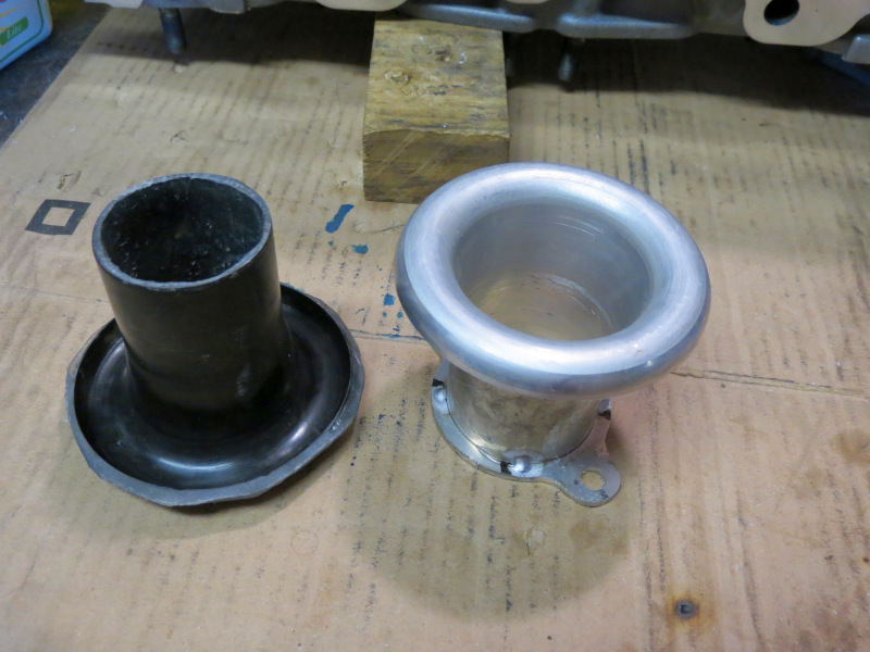
First order of business was to start making my own 50mm ID velocity stacks, as I’m unable to source some in the country and the imported units are very expensive. The best strategy my brother and I could come up with was to make a mould of one of his 48mm ID x 65mm High ITG units, once this was done I basically destroyed it in a lathe trying to open the ID to 50mm. In the mean time I bought a carbide insert boring bar for the lathe, this time around I’ll make a much stronger unit to clamp more securely to the chuck and use the sharpest possible tools.
As I was busy figuring out what would the best solution be to make my own throttle linkage, I noticed one of the roller needle bearing was missing and another one badly damaged, these was replaced by new HK1210 units. Here is a very good link to help with a few ideas to make your own puller, unfortunately the E46 units have a shoulder that does not allow a bolt to pull thru the housing, I had to get creative by breaking a quarter out of the bearing housing after removing all the rollers, then grinded 3/4 of a M8 countersink Allen cap to get a snug fit inside the bearing casing in order to pull it out, with allot of heat applied.
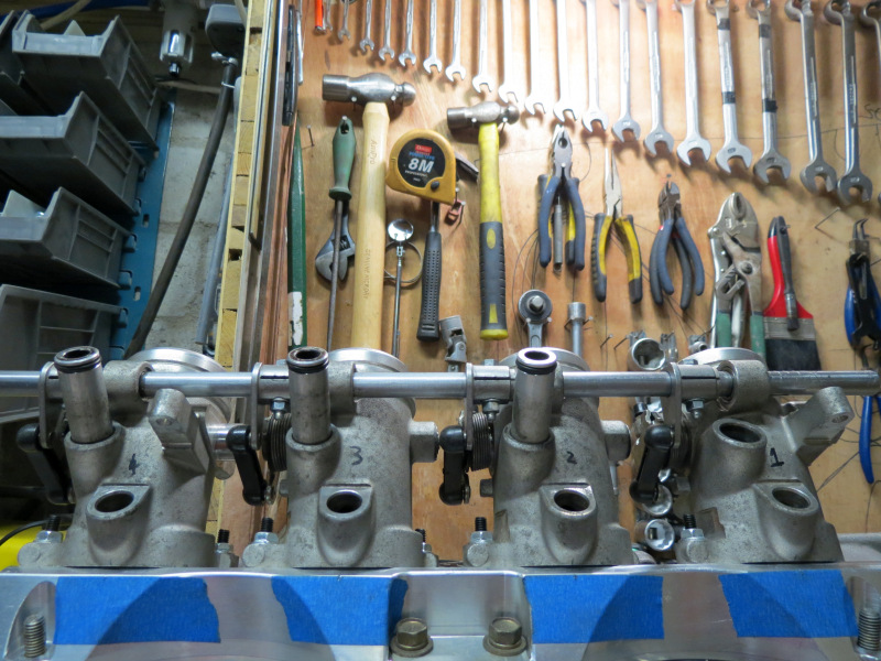
As for the shaft between the throttles a piece of 12mm OD Zista tubing was polished in the lathe to get rid of that 0.1mm to enable it to pass thru the new needles and cams that actuate the butterflies. I just need to turn a few Polypropylene bushes to restrict movement of the shaft. Once this was in place I was able to measure the amount of travel on the cable to allow the full use of the throttle pedal range, this then was used to determine the size of the cam needed to pull the shaft thru 90 degrees to open the throttles from close to open. This would give the best possible throttle pedal modulation with what I have available. I managed to finish the mounting for the throttle cable, even if this is not my best work to date, it is done, I’m pretty sure something is disturbing the Argon flow out of the TIG torch as you can feel it, but it is as if it is not directed to the tungsten tip. In the next few days I’ll make an adjustable mount for the throttle cable cam.


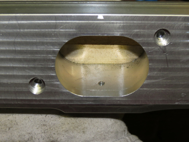


Seeing that I wanted to keep the vacuum take off separate from the Idle control manifold for the best possible readings, I came up with a plan that involves drilling and tapping into the beautiful adapter. Trust me on this one, I triple triple checked everything, seeing that I was not willing to mess up and replace the adapter. I( purchased a few weld on banjo’s and set about drilling and tapping holes for the 10mm banjo bolts, I even had to get creative by cutting a piece of wood to the exact angle in order to clamp the adapter in order to drill the holes 90 degree to the face. Afterwards I made a nice big reservoir from 30mm pipe to remove as much possible pulses from the vacuum readings. I even had to mill the heads smaller on the banjo bolts to clear the water temp sensor. The unit will have two take offs, one for the MAP sensor and the other for the Fuel Pressure Regulator.


Next inline was the Idle Control Manifold, as I only got 3 of the original connectors between throttle body and reservoir tube, I became creative and made my own one on the lathe and a piece of 20mm OD Aluminium pipe rounded off the reservoir and link between the standoffs, I had a few brackets laser cut to mount and strengthen the unit, once more of the pieces is in place I’ll add probably a -8AN male alu plug for the intake, I’m pretty sure -10AN is overkill for idling, it is not as if I want to use the intake to blip the throttle, hmmmm, maybe this idea could work, I’ll have to spend some time on it.
Fuel Rail
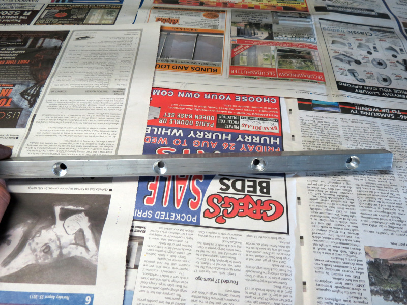
I tried my absolute best to try and find a way to use the old SR rail, but it turned out to be an unfruitful exercise as I would have to make adapters to space the rail away from throttle bodies, thus ruining the spray pattern of the injectors, it was to just do it correct from the start, I spend countless hours researching injectors as an injector previously was just an electrical solenoid opening and closing to allow fuel to enter the combustion chambers, well not any more. I more or less decided on the design needed that will be easy to make a rail, available connectors, size and spray pattern. At the end of the day I settled for a set of brand new Bosch 0280156127 440cc 42lbs-hr EV6 Blue Giant units, seeing that they have a very thin body and with a dual wide cone spray pattern, made them ideal for the SR head with the divider in the intake port. Being armed with all these new knowledge regarding injectors, I bought a piece of aluminium fuel rail from Flat Four Racing for a very decent price. On this subject, what kind of business opens at 9am and closes at 3pm in these days, it is virtually impossible to get to them during the week. Anyways, the holes was drilled very carefully again, luckily with the mill in the garage the finish on the holes was perfect for using a normal drill bit as we don’t own a 14mm end mill. Now I just have to wait for the injectors to arrive from the States in order to finish the mountings on the rail. All the brackets and reinforcements have already been laser cut and is just sitting and waiting.

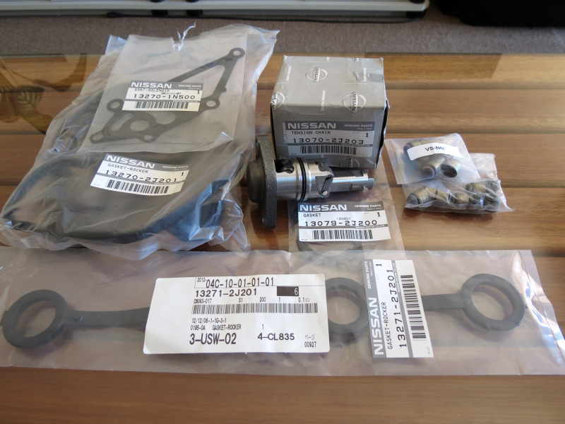
During this time RAW supplied me with another box of goodies to get the motor together in the form of a Cometic gasket, ARP Head Studs and some fancy NGK plugs. Also a separate order from the States arrived with more original Nissan OEM parts than ever graced my parts collection.


Port Polishing
It took more or less 3-4 weeks for the machine shop to finish with the head, once it came back, I decided that I will remove all the casting marks on the intake and exhaust ports, finishing the job by polishing the exhaust ports and combustion chamber to the smoothest finish I can manage and treat the intake adapter and ports with some rough sanding paper. My only rule before I started was that I will not touch the head with a carbide cutter as I don’t have enough experience with it, yes chuckle all you want, but we all know a die grinder only follows its own head. I used a lot of sanding barrels and flap wheels to get rid of the cast marks and to polish all the ports, then the intakes was roughed with some 36 grid sanding paper and the exhaust and combustion chambers polished with my home made cross-buffs. At the end of the day I’m very happy with the outcome, I’m pretty sure the time (about 9-10 hours) and money spend to do this will not result in a mayor power increase if any, but I learned allot and it would just feel as if I did my best on the head before re-installing it.
More Pictures – February 2013 – Damn, Upgrades this soon
Return to Datsun 1200